


EasyCASE is one application that is used to design a workflow system or better known as DFD (Data Flow Diagram). DFD is very important to analyze the course of the system. The flow of this system reflects the performance of a system. Unlike the other applications, EasyCase gave token of the mistakes made so that the depiction of the output that comes out is actually output by the rules and symbols of each methodology.
There are several options methodology and process model data offered by this application relating to the depiction of the flow system, ie
1.
a. Process Model
b. Yourdon (DFD)
c. Gane and Sarson (DFD)
d. SSADM (DFD)
2.
a. Data Model
b. Martin (ERD and DMD)
c. Merise (ERD)
d. Shlaer-Mellor (ERD)
e. SSADM (ELS and ELH)
f. Each methodology has different symbols and rules.
Here is an example DFD generated EasyCase.
1. Choose a start - and then press the easy case professional Program 4:23 - then at a click. Easy case such as that displayed in the following figure:
2. The next step in the case of professional eassy menu select and click on the file and select the project and on click
3. langah subsequently created in the storage directory and then create a folder in that directory contonya D: \ 06141010 \ Practicum 2 that means we keep our project in Drive D with 06,141,010 directory name. see in the picture below:
4. next steps write an appropriate project name project name and select the icon Define Contact the diagram.
5. type the name of the context diagram on Contack name then ok then ok again. Perhatihkan the following picture:
6. The next step after as above and then click on the diagram define Contack as written click here, the image appears as follows:
7. Then click Ok then Ok again and will appear as follows:
8. Then will appear the dialog as follows:
9. Click Ok to eat will be performing the layer where we design the DFD as follows seseuai screen can be enlarged with the desire. And we can make disaing DFD by creating a process in the context diagaram first. But in Case Eassy usually standard diagram will appear automatically be confirmed over at the click Ok. 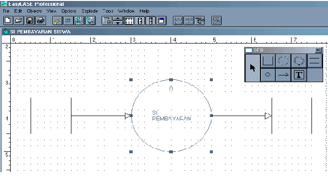
10. From the figure is still above the standard and simple as we can process it and give the name and so on, as follows:
11. With Double-click on the symbol that will be given a name and description given in it to follow up the following dialog appears, then click yes.
12. after select yes will appear as follows:
13. Select the appropriate Type Chil PPS on the image above and then click Ok, can also be done by right-clicking on the object / symbol DFD then select difine Child as above but with way more quickly.
14. Then give a brief description of the dialog text editor, then click Save and then select Close, "This command can also be done primarily to right-click on the object and then pili goto child. 
Bisa Download Software Disini !
Do you like this article? Share It!


0 komentar to "Steps in the manufacturing context diagram using professional easycase 4:23"
Postingan Populer
-
 EasyCASE is one application that is used to design a workflow system or better known as DFD (Data Flow Diagram). DFD is very important to an...
 -
this time I will tell you how my steps in creating a shared network folder settings in Windows 7. The steps to perform this setup is actuall...
-
Antivirus is a type of software used to detect and remove computer viruses from computer systems. Also called Virus Protection Software. Thi...
-
1. What is a virus? A computer virus is a small program that can copy itself in a computer storage media. Formal is as follows: "A prog...
-
a. Information systems Information System consists of two words namely Systems and Information. The system itself is a composite of several ...
-
Virus attacks can be prevented or overcome by using antivirus software. This type of software can also detect and remove computer viruses, p...

Posting Komentar